
Product series:
DZ-968 Auxiliary Steering Gear
SanOu offer a full line of competitive products,that was regulator power supply,spacer,regulator box,intergration speaker,GPX fix sensor,magnetic fix sensor,dadar shell,automotic rudder,speaker etc.

Description
SanOu offer a full line of competitive products,that was regulator power supply,spacer,regulator box,intergration speaker,GPX fix sensor,magnetic fix sensor,dadar shell,automotic rudder,speaker etc. With the "Credit" as its business idea, SanOu will do the best to serve their customers for the good future.
Marine ancillary products refer to all marine equipment and devices except the hull, which is an important part of the shipbuilding industry. These products cover a wide range of equipment and systems required for navigation, operation, safety and daily operation of ships. Specifically, marine ancillary products mainly include the following categories: Power equipment: such as ship main engine, auxiliary engine, steam boiler, thruster, shafting, etc., which are the core equipment that provides ship power and power. The main engine of a merchant ship is usually the ship's diesel engine, while the auxiliary power unit is the ship's generator, which provides electrical energy for the ship in normal and emergency situations. Maneuvering equipment: including steering gear, steering gear, autopilot, remote control system, etc., which are used to control the course, speed and attitude of the ship. Loading and unloading equipment: such as cranes, cranes, conveyor belts, etc., used to realize the loading and unloading and transportation of goods.
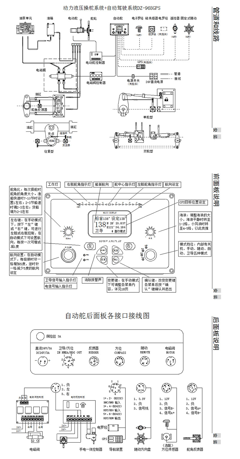
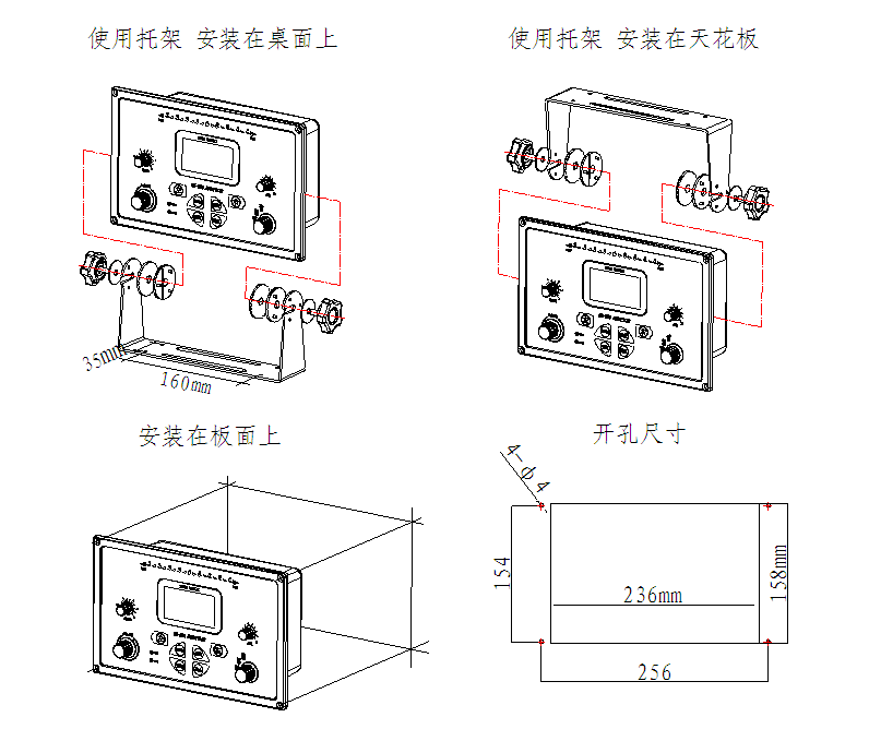
I. Control Unit Installation
1. Control Unit DZ-968GPS
Since the control unit uses many sophisticated electronic and electrical components, the installation location should meet the following requirements:
1. Should be installed in a place with low humidity.- 2) Easy-to-operate areas
- 3) Places that are easy to install and maintain
- 4) Areas not directly exposed to seawater or sea breeze
5) Do not expose directly to sunlight.
6) Places free from vibration
Attention: Do not install this unit in locations subject to severe vibration or direct exposure to seawater, sea breeze, or rainwater. Otherwise, the unit may malfunction, leading to steering failure.
2. Installation of the flashlight-integrated connector
1. Integrated flashlight installation instructions
On a vessel equipped with a steering gear, install the integrated flashlight connector onto the steering gear and secure it to the housing; then simply attach the steering wheel.
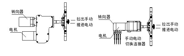
Pull out the central pull rod, and steer using the steering wheel; push the middle handle forward, and the steering wheel will separate and be steered by the motor.
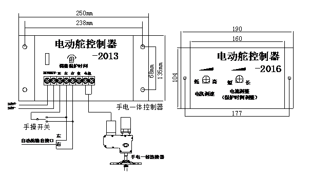
2. All-in-one flashlight controller
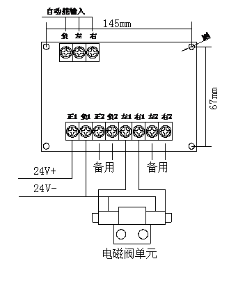
Install the control box in a well-ventilated and dry location, and connect all accessories and power cables according to the wiring diagram printed on the control box. When you apply 24V power, the alarm light will flash and an alarm sound will be emitted. At this point...
The system is in an alarm state. Please press the reset button; the alarm light will turn off, the alarm sound will stop, and the controller will enter the operating state.
3. Solenoid Valve Control Board
Attention: Do not install the solenoid valve control board in locations subject to severe vibrations or direct exposure to seawater, sea breeze, or rainwater. Otherwise, the unit may malfunction, leading to steering failure.
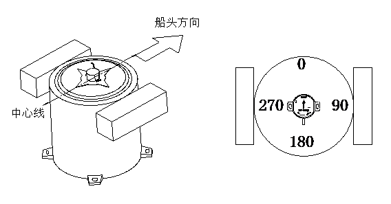
3. Installation of the Magnetic Azimuth Sensor
Because the orientation sensor is highly sensitive to magnetic fields, it will be affected when the magnetic field around its installation location changes. During autonomous driving, a sudden change in the magnetic field...
The magnetic field generated by the device (such as solenoid valves, motors, etc.) could cause the ship to turn sharply and pose a danger. Therefore, the orientation sensor must be kept at least 50 cm away from such devices that produce magnetic fields, and this must be confirmed.
It will not be affected by this magnetic field, so magnetic tools or objects are prohibited from being placed nearby.
*Install the magnetic compass along the ship’s centerline or in a position parallel to the centerline, and ask the compass operator to calibrate the magnetic compass. This will improve the accuracy of the ship’s heading during autopilot operation.
*Align the pointed end of the azimuth sensor with the center line of the magnetic compass. Peel off the adhesive paper on the bottom of the azimuth sensor and affix it to the center position on the front side of the magnetic compass. Then, align the...
Properly secure the cable of the position sensor.
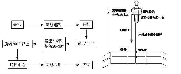
4. Installation and Debugging of the Electronic Compass
Point the electronic compass antenna arrow toward the bow of the vessel, secure it with adhesive tape to a bamboo, wooden, or stainless steel pole—preferably one that is more than 1.5 to 2 meters long and non-magnetic—and install it on the helm.
On the railing at the top of the cab, within a one-meter radius—up, down, left, right, forward, and backward—there must be no ferrous or magnetic objects, preferably positioned as close to the center as possible.
*Note: Do not install on iron rods or on the side of a boat.
Electronic compass antenna calibration diagram in tabular form:
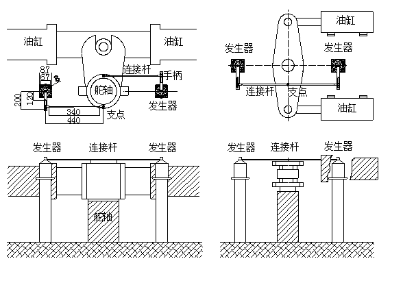
5. Installation of the Rudder Angle Generator
*The rudder angle generator can be installed at the front, rear, left, or right of the rudder; the specific installation location should be determined based on the cabin’s layout and the actual conditions of the system.
*Straighten the ship’s rudder, and install the generator at a point parallel to the center of the main rudder bracket. The center of the rudder shaft should be the same length as the distance between the generator’s center and the two mounting holes on the connecting rod. The generator handle should align with the rudder.
The axis center is the same length as the fulcrum, ensuring that the generator is aligned parallel to or in a horizontal position with the rudder bracket.
*Note: Parallel installation can provide the host with feedback on the actual angle of the rudder.
Note: Adjusting the rudder angle to the neutral position is a crucial step, as it directly affects the vessel's navigation accuracy and the operating frequency of the solenoid valves.
Keyword:Shipping equipment,Boat Parts,Sanou
Satellite compass
Auto-pilot/Control Console
Electric throttle/hydraulic controller
Voltage regulator power supply/voltage regulator box
Steer the steering wheel
Rudder angle indicator/Revolution counter
Transmitter/Electric horn/Microphone
Monitor/Alarm/Signal Clock
Charger/Charging Station/Welding Machine
Marine antenna
Ship lighting lamps
Radar accessories
Signal distributor
Related Download
Recommended Products